
What Inspection Standards Should Buyers Know for Nickel 201 Foil?
- Nickel 201 Foil
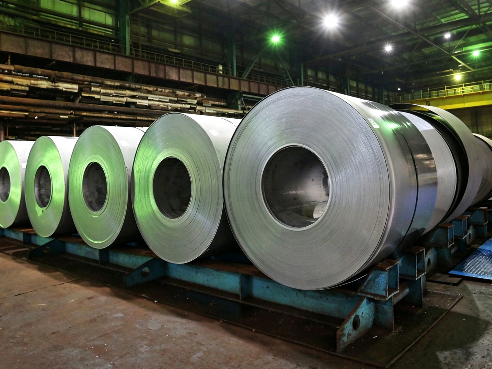
Many buyers, after receiving the material certificate, consider the material acceptable upon seeing Ni ≥ 99.0%, C ≤ 0.02%. In reality, however, incoming inspection of Ni201 foil involves far more than chemical composition alone. Thickness tolerance, surface cleanliness, mechanical properties, annealed microstructure uniformity, and other factors can all directly affect downstream yields in stamping, welding, coating, or electroplating. From the perspective of procurement acceptance, this article outlines the main inspection dimensions for Ni201 foil as a reference for developing incoming inspection documents.
1. Chemical Composition and Low-Carbon Requirements
The most fundamental difference between Ni201 (UNS N02201) and Ni200 (UNS N02200) lies in the carbon content. C ≤ 0.02% is the core technical requirement of Ni201 and the fundamental reason it is less prone to graphitization embrittlement during long-term service below approximately 600℃. When purchasing, simply specifying high-purity nickel is insufficient; buyers should explicitly require suppliers to provide a full chemical composition report conforming to the requirements of ASTM B162 / UNS N02201.
(1) Requirements for major element contents
Element | Standard Limit |
Ni (incl. Co) | ≥ 99.0% |
C | ≤ 0.02% |
Fe | ≤ 0.40% |
Mn | ≤ 0.35% |
Si | ≤ 0.35% |
Cu | ≤ 0.25% |
S | ≤ 0.01% |
Excess carbon content is one of the common reasons for batch rejection. It is recommended that the purchase contract explicitly require heat-level spectroscopic analysis reports rather than relying solely on aggregated data.
(2) Why sulfur content should not be overlooked
Although the sulfur content limit is low, it still requires close attention. Sulfur readily segregates at grain boundaries and adversely affects hot workability and weldability. For applications requiring welding or hot forming, sulfur content should be treated as a key verification item rather than assumed to be automatically compliant.
(3) Recommended test methods
ICP-OES (inductively coupled plasma optical emission spectrometry) is recommended for full-element quantitative analysis; infrared absorption is recommended for dedicated carbon and sulfur testing. These methods offer high accuracy and reproducibility and are better suited to incoming acceptance of electronics-grade and chemical-grade nickel foil.
2. Dimensional Tolerances and Flatness Control
Dimensional tolerances and flatness directly affect compatibility with automated production lines. Tolerance deviations mainly cause out-of-tolerance finished dimensions, assembly interference, or poor welding alignment. At the time of purchase, the tolerance class, measurement method, and sampling locations should be specified in the contract or acceptance specification, avoiding a mere statement of meets standard without defining the specific class.
(1) Reference ranges for thickness tolerance and measurement essentials
The ranges below are for reference by both supplier and buyer for precision foil and should not be used directly as a universal acceptance criterion for all specifications. Actual acceptance shall be governed by the standard clauses and tolerance class agreed in the contract.
Thickness Range | Reference Tolerance | Measurement Tool | Remarks |
0.03-0.05 mm | ±0.002 mm; ±0.001 mm negotiable | Laser thickness gauge or digital micrometer | Measurement resolution and repeatability must be verified |
0.05-0.1 mm | ±0.003 mm | Laser thickness gauge / digital micrometer | Edge thinning to be separately agreed |
0.1-0.3 mm | ±0.005 mm | Digital micrometer / thickness gauge | Sampling interval and location must be defined |
0.3-0.5 mm | ±0.008 mm | Digital micrometer | May reference GB/T 2072 or ASTM B162 tolerance classes |
0.5-0.8 mm | ±0.010 mm | Digital micrometer | Same as above |
Measurement should be performed at room temperature under no-tension or low-tension conditions, with measuring points distributed at equal intervals across the width, for example at least three points. For very thin gauges with a thickness of ≤0.1 mm, some precision rolling mills can control the thickness tolerance to within ±0.001 to ±0.002 mm, but this precision should be justified by actual measured data and measurement system capability. For gauges above 0.5 mm, an overly strict statement such as ±0.001 mm should not be applied.
(2) Width tolerance and edge quality
Width tolerance may reference GB/T 2072 or the contract agreement; a common requirement is ±0.5 mm. Measurement may be performed with a steel tape measure or a vision/image measuring instrument; it is recommended to measure at least one location at each of the head, middle, and tail of every coil.
The slitting burr height may be specified as not exceeding 10% of the material thickness, with sampling performed using an optical microscope or profilometer at equal intervals along the length of the slit edge, for example no fewer than five points. Where necessary, maximum and average value requirements should also be agreed rather than specifying only a single proportional upper limit.
(3) Flatness and warpage control
Flatness acceptance must distinguish between thickness, width, coil diameter, and measurement baseline; a criterion such as warpage not exceeding 2 mm over a 1 m length should not be used as a universal threshold for all specifications. For wide thin foil below 0.1 mm, natural flat placement or low-tension unwinding may be used, with the sampling length and measurement spacing agreed in advance; for thicker narrow strip, the warpage height per meter may be agreed as specified in the contract.
Leveling treatment may improve macroscopic warpage, but it can also introduce residual stress or alter the surface condition. Whether leveling is required should be evaluated in conjunction with the downstream forming process; leveled product should not simply be assumed to be superior to unleveled product.
3. Mechanical Properties and Supply Condition
Typical supply conditions of Ni201 foil include annealed and cold-rolled/hard. Performance differs significantly between conditions and must be clearly specified according to the downstream forming, joining, or load-bearing requirements. Tensile property data should be judged in conjunction with thickness, cold-rolling reduction, hardness condition, and sampling direction; a given range should not be used directly as a universal acceptance value for all specifications.
(1) Reference typical mechanical properties
Supply Condition | Condition Designation | Tensile Strength | Yield Strength (0.2% Offset) | Elongation | Reference Vickers Hardness HV | Remarks |
Annealed | Annealed | 380-550 MPa | 100-250 MPa | ≥40% | 80-130 HV | Typical range; specific minimum/maximum values to be confirmed between supplier and buyer |
Cold-rolled / hard | Cold-rolled / Hard | 550-750 MPa or higher | 300-600 MPa | 2%-10% | 140-220 HV | Range varies with cold-rolling reduction and hardness grade; not suitable as a universal acceptance range |
If the annealed condition is used for deep drawing or bending, an elongation of ≥40% should be used as the reference minimum rather than only requiring ≥25%. If the cold-rolled/hard condition is accepted only on tensile properties, the cold-rolling reduction, hardness upper limit, and sampling direction should also be specified; if downstream bending is required, a bend test or hardness upper limit is recommended as a supplementary criterion.
(2) Annealed microstructure uniformity
For gauges above 0.3 mm, the grain size may reference ASTM No. 4-7; for ultra-thin foil of 0.03-0.1 mm, a finer grain size is preferred, for example ASTM No. 6-8 or finer, to avoid grain dimensions approaching or exceeding the material thickness, which would cause non-uniformity in surface and mechanical properties.
During continuous annealing, attention should be paid to furnace temperature setpoint accuracy, furnace temperature uniformity, strip travel speed, and the actual material temperature; the temperature displayed by the equipment controller should not be equated directly with the material heat treatment temperature. Suppliers should be asked to provide annealing process curves and batch metallographic photos.
(3) Hardness testing and work-hardening assessment
For cold-rolled/hard Ni201 foil, Vickers hardness can effectively assess the degree of work hardening. It is recommended that at least three transverse positions and two longitudinal locations at the head and tail be sampled per batch to verify hardness uniformity. Excessively high hardness may indicate excessive cold-rolling reduction or insufficient annealing, increasing the risk of cracking; excessively low hardness may indicate over-annealing and reduced strength.
4. Surface Quality and Downstream Process Suitability
(1) Classification and judgment of surface appearance defects
Common surface defects include scratches, oxidation color variation, rolling laps/folds, pinholes, and inclusions. Visual inspection may be performed as 100% manual inspection or automated optical inspection under uniform diffuse lighting.
Pinholes should be detected with an online pinhole detector or a transillumination light box, with the minimum detectable diameter and inspection coverage agreed in advance. Inclusions may be scanned with ultrasonic or eddy current methods, but the resolution for thin foil is affected by thickness, frequency, and probe matching; verification by metallographic cross-section is recommended. The acceptance documents should also specify sampling locations, quantities, and defect classification criteria.
Pinholes and inclusions pose higher risks in applications such as battery tabs and electrolytic electrodes, as they may create localized current density concentration, pitting initiation sites, or coating defects; however, not all inclusions will immediately cause corrosion perforation. Control should be achieved through limits on size, distribution, and quantity.
(2) Surface cleanliness and wettability
The cleanliness of metal foil should not be judged by the dyne value alone. The dyne value is affected by the oxide layer, surface topography, storage environment, and test conditions, and is more appropriately used as a reference for surface energy. For Ni201 foil used in adhesive bonding, welding, or electroplating, the acceptable range should be established through downstream process validation, taking into account indicators such as contact angle/surface energy, water-break test, particle residue, or ionic contamination.
Clean metal surfaces generally wet well, but the specific dyne value or contact angle requirement should be determined from process validation data and should not be treated as a universal threshold for battery-grade or electronics-grade material.
(3) Surface condition and downstream processing compatibility
The choice between bright and matte finishes should be evaluated in conjunction with the oxide film, roughness, contact pressure, and test conditions. A clean bright finish generally provides lower contact resistance and higher reflectivity, suiting applications requiring electrical conductivity or optical appearance; a matte finish, owing to its higher roughness, may offer better mechanical anchoring for coatings or composite layers, but the adhesion result depends on the surface pretreatment, coating system, and curing process. Contact resistance or adhesion cannot be judged acceptable based solely on surface condition.
5. Standard Compliance and Quality Documents
(1) Core quality documents recommended for request
Document Type | Content Requirements |
Material certificate | Heat number, chemical composition, supply condition, mechanical properties, heat treatment records |
Dimensional inspection report | Measured values of thickness, width, length, and flatness, plus measurement methods |
Surface inspection report | Appearance defect assessment, pinhole test results, surface wetting/cleanliness data, with test methods and acceptance limits noted |
Standard compliance statement | ASTM B162 / UNS N02201 compliance statement and additional statements for special agreements |
(2) Distinguishing ASTM B162 from additional inspection requirements
ASTM B162 mainly provides general requirements for chemical composition, dimensional tolerances, mechanical properties, and sampling rules. Dyne value, pinhole limits, ionic contamination, surface cleanliness, and similar parameters are generally outside the mandatory scope of the standard and should be written into the purchase contract or an additional technical agreement. An ASTM B162 compliance statement alone cannot be used to infer that surface quality meets battery-grade or electronics-grade requirements.
(3) Batch consistency and process capability
Batch consistency should be assessed through supplier process capability data, such as CPK, thickness distribution histograms, heat-to-heat chemical composition variation, and tensile property statistics for the same specification in recent production. Buyers may require suppliers to provide samples and process statistical records to judge quality stability; quality should not be inferred solely from production capacity.
6. Conclusion
Incoming inspection of Ni201 foil should cover five modules: chemical composition, dimensions and flatness, mechanical properties, surface quality, and quality documents. Acceptance criteria should match the supply condition, thickness specification, and downstream process; a single value should not be used directly as a universal criterion for all batches. By defining clear purchase specifications and retaining measured data, the risk of batch-to-batch variation can be reduced more effectively.
FAQ
(1) Q1: What is the most important difference between Ni201 and Nickel 200 in inspection standards?
The most critical difference is the carbon content: UNS N02201 is a low-carbon nickel normally required to have C ≤ 0.02%, while UNS N02200 permits a higher carbon content, for example C ≤ 0.15%. This difference means Ni201 is significantly less prone to graphitization embrittlement below approximately 600℃. A Ni200 report cannot be substituted for a Ni201 report; carbon content data must be verified separately.
(2) Q2: When purchasing ultra-thin Ni201 foil of about 0.03 mm, which inspection items most often present problems?
The most common problems fall into three areas: thickness uniformity across the width, control of slitting burr height, and surface oxidation color variation after annealing. Thickness uniformity can be assessed by multi-point thickness measurement across the width with data recording; burr height should be sampled with an optical microscope or profilometer; the post-annealing surface condition should be confirmed against limit samples and inspection records.
(3) Q3: What is the practical significance of dyne value testing on Ni201 foil?
The dyne value can serve as a surface energy reference to help judge wetting tendency, but it is not directly equivalent to coating adhesion, weld wetting, or electroplating bond strength. It is mainly affected by the oxide layer, surface topography, test liquid, temperature and humidity, and surface contamination. If this indicator must be used, the test conditions, test locations, and process-validated acceptable range should be clearly specified, in conjunction with surface pretreatment and process validation, to avoid treating a fixed value as a universal acceptance line.
Contact Us
Titanium Valley is a manufacturer and supplier focused on the precision processing and supply of titanium, nickel, and zirconium materials, with an annual production capacity of 20, 000+ tons of titanium bars and wires. We provide customized production and volume supply of Nickel 201 foil to customers in the chemical, medical, marine engineering, and precision electronics industries worldwide. Please contact us at: sales@titaniumvalleys.com
References
- National Technical Committee on Nonferrous Metals Standardization. GB/T 2072-2007 Nickel and nickel alloy strips[S]. Beijing: Standards Press of China, 2007.
- National Technical Committee on Nonferrous Metals Standardization. GB/T 2054-2005 Nickel and nickel alloy plates[S]. Beijing: Standards Press of China, 2005.
- National Technical Committee on Nonferrous Metals Standardization. GB/T 5235-2008 Wrought nickel and nickel alloy – Grades and chemical composition[S]. Beijing: Standards Press of China, 2008.
- Huang Boyun, Li Chenggong, Shi Likai, et al. China Materials Engineering Canon, Volume 4: Nonferrous Metals Materials Engineering (Part 1)[M]. Beijing: Chemical Industry Press, 2006.
Published by: Titanium Valleys
Technical review: General Manager of the Production Department
Quality review: Quality Inspection Department
Last reviewed: October 20, 2026