
What Are the Thickness Specifications and Selection Guidelines for Gr1 Titanium Foil?
- Gr1 Titanium Foil
Direct engineering answer. Gr1 Titanium Foil should be evaluated against the finished component, product form, governing specification, downstream process and acceptance evidence. A general property value is an orientation tool; the released drawing, current certificate and inspection plan control the final decision.
Grade 1 titanium foil (Gr1 Titanium Foil) is a higher-purity grade within commercially pure titanium, with a titanium content ≥99.5%, offering good ductility, corrosion resistance, and biocompatibility. However, when actually selecting material, one should not only consider the material grade; thickness must also be treated as a key engineering parameter. Thickness directly affects the foil’s formability, weight per unit area, stiffness, load-bearing capacity, electrical resistance and current-carrying capacity, as well as the suitability of downstream processing operations. It should be particularly noted that thickness does not determine the material’s inherent electrical conductivity, which is primarily governed by resistivity; thickness affects electrical resistance or current-carrying capacity. This article reviews the thickness segments, tolerances, properties, and typical applications of Gr1 titanium foil over the thickness range of 0.02 mm to 1.0 mm, as a reference for material selection in aerospace, new energy, electronic packaging, chemical anti-corrosion, and other fields.
1. Overview of Gr1 Titanium Foil Thickness Specifications: From Ultra-Thin Foil to Precision Strip
(1) Main Thickness Range Divisions
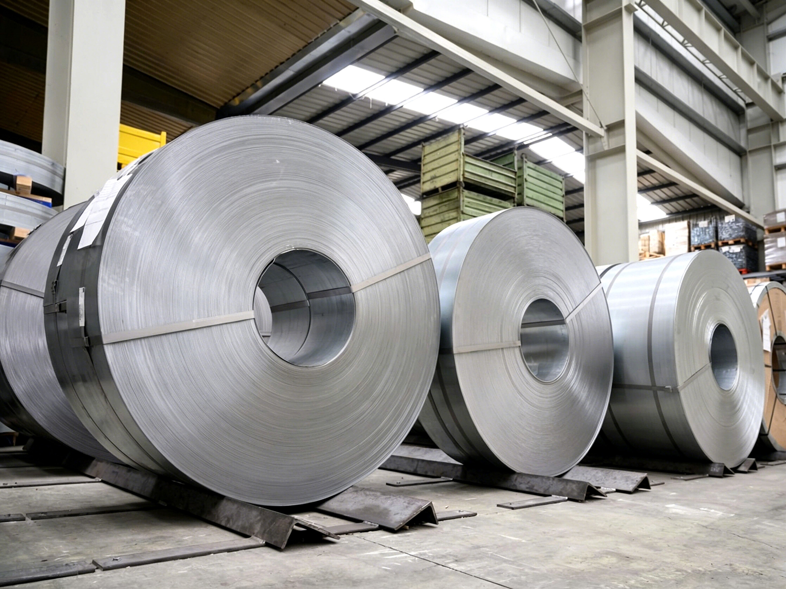
The commonly supplied thickness range of Gr1 titanium foil is 0.02 mm to 1.0 mm, with widths covering 350 mm to 670 mm, supplied in coil/strip form, and length customizable as required. To avoid overlap between thickness ranges, the following segmentation boundaries are recommended:
- Ultra-thin foil: 0.02 mm ≤ t < 0.10 mm
- Thin strip: 0.10 mm ≤ t < 0.50 mm
- Precision strip: 0.50 mm ≤ t ≤ 1.0 mm
The rolling difficulty, shape control, surface quality requirements, and mechanical property emphasis of the three ranges differ significantly, and material selection should not be loosely treated as merely “thin” versus “thick.”
(2) Manufacturing Approaches and Property Evaluation for Ultra-Thin Specifications
Achieving stable rolling at the 0.02 mm level typically relies on multi-roll precision mills, such as 20-high mills, for multi-pass finish rolling, combined with tension control, shape roll correction, and intermediate annealing. The main difficulties lie in large springback, shape fluctuation, and control of microstructural uniformity. Annealing is generally performed as continuous argon-protected annealing. Furnace temperature control accuracy should be set based on furnace type, line speed, and atmosphere conditions; it is inappropriate to simply characterize the continuous annealing of wide, large coils as “±2℃.” Likewise, elongation should not be attributed solely to annealing temperature tolerance. Elongation is affected by multiple factors including material composition, cold rolling reduction, annealing temperature and time, cooling conditions, and specimen thickness and gauge length. For tensile testing of 0.02–0.10 mm ultra-thin foil, small gauge length specimens are recommended per GB/T 228.1, and the specimen gauge length should be noted in the report. The elongation values used for thin or thick sheets under their gauge lengths cannot simply be applied.
(3) Standard Thickness Specification Reference Table
The following table summarizes the typical thickness specifications of Gr1 titanium foil and the corresponding technical requirements for material selection reference.
Thickness Range | Typical Specifications (mm) | Thickness Tolerance | Main Width Range | Supply Condition |
Ultra-thin foil 0.02≤t<0.10 | 0.02 / 0.03 / 0.04 / 0.05 / 0.06 / 0.08 | ±0.001 mm (typical internal control value, subject to agreement) | 350–670 mm | Annealed (commonly used); cold-rolled/hard condition per agreement |
Thin strip 0.10≤t<0.50 | 0.10 / 0.15 / 0.20 / 0.30 / 0.40 | ±0.002–0.004 mm (segmented by thickness) | 350–670 mm | Annealed (commonly used); cold-rolled condition per agreement |
Precision strip 0.50≤t≤1.0 | 0.50 / 0.60 / 0.70 / 0.80 / 1.0 | ±0.005–0.010 mm (segmented by thickness) | 350–670 mm | Annealed (commonly used); cold-rolled condition per agreement |
> Note: Non-standard thicknesses such as 0.07 mm and 0.12 mm may be supplied by agreement, but tolerances, shape, edge quality, and inspection items should be specified at the time of ordering. Actual thickness tolerances are governed by GB/T 3622, ASTM B265, or the technical agreement between the supplier and purchaser.
2. Property Characteristics and Suitable Applications for Different Thickness Ranges
(1) Ultra-Thin Foil (0.02≤t<0.10 mm): A Carrier for Lightweighting and Precision
Titanium foil in this thickness range has a low weight per unit area and is suitable for applications with high demands on weight, space, and thinness. For property data such as tensile strength and yield strength, a distinction should be made between “standard minimum values for annealed thin sheet” and “measured values for ultra-thin foil”; thick-sheet data cannot be directly applied to ultra-thin foil.
Typical mechanical property reference values for annealed Gr1 thin sheet/strip:
Property Parameter | Value |
Tensile strength | ≥240 MPa |
Yield strength | ≥170 MPa |
Elongation | ≥24% (thin sheet gauge length 50 mm; for ultra-thin foil, note the small gauge length and report measured values) |
Hardness | 120–160 HV0.5 (micro-Vickers hardness, typical annealed value) |
Density | 4.51 g/cm³ (approximately 57% of steel) |
Typical applications include fuel cell bipolar plate substrate materials, precision sensor diaphragms, thin-wall non-primary load-bearing structural parts, honeycomb sandwich liners, and thermal protection or insulation pads. Whether ultra-thin foil is suitable for primary load-bearing aircraft parts such as skin should be determined based on specific structural design and test verification and cannot be judged by thickness specification alone.
(2) Thin Strip (0.10≤t<0.50 mm): A Balanced Range of Formability and Strength
In the 0.10–0.50 mm range, Gr1 titanium foil balances formability and load-bearing capacity and is a commonly used thickness range in industrial applications. This specification can be formed by bending, stamping, deep drawing, and other processes and offers good welding stability. After ultrasonic + alkaline solution cleaning, the wetting tension measured per GB/T 14216 typically reaches 44 mN/m, i.e., 44 dyn/cm. However, this value changes with storage time and environment and should be re-verified before use. Although cleaning can meet the initial surface requirements of some processes, activation, degassing, or other pretreatment is still required before coating, anodizing, brazing, and other operations according to the specific process requirements; it cannot be assumed that “no additional pretreatment is needed.”
(3) Precision Strip (0.50≤t≤1.0 mm): A Reliable Substrate for Structural and Functional Components
Gr1 titanium foil above 0.50 mm is closer to thin sheet, offering higher rigidity and pressure-withstanding capability, and is commonly used for chemical equipment linings, heat exchanger plates, and electrolyzer electrode substrates. This thickness range places high demands on flatness and shape control, typically requiring flattening tension optimization and dedicated levelers to reduce distortion and scrap rates in subsequent stamping, stacking, and welding operations. When selecting material, priority should be given to thickness tolerance, shape, edge quality, and surface condition. Corrosion resistance should be evaluated based on the specific medium and temperature rather than judged by thickness alone.
3. Core Considerations in Thickness Selection
(1) Service Environment Determines the Lower Thickness Limit
The starting point of selection is to clarify the stress state and service environment of the part. Gr1 has good corrosion resistance in oxidizing, neutral, and most chloride-containing environments, but corrosion may occur in strongly reducing acids, high-temperature concentrated chlorides, and other conditions; therefore, it cannot be simply stated that “the corrosion resistance of the titanium foil itself is sufficient.” If fluid erosion or mechanical abrasion is present, overly thin foil may fail prematurely due to corrosion, wear, or localized perforation. Generally, for chemical anti-corrosion linings, a thickness of 0.50 mm or more is recommended; for lightweight applications such as fuel cell plates and precision electronic corrosion-resistant packaging, 0.05–0.20 mm can be considered; for medical implants and precision instruments, the optimum thickness should be determined in combination with mechanical calculations and biomechanical requirements.
(2) Processing Technology Determines the Upper Thickness Limit
Downstream processing methods also impose constraints on thickness. Laser cutting and precision blanking perform well on ultra-thin foil, but processing parameters may need to be adjusted once thickness exceeds 0.5 mm; deep drawing requires good material ductility, and Gr1 in the annealed condition has good ductility, but the specimen gauge length should be noted for ultra-thin foil elongation; resistance welding and argon arc welding can generally be operated stably within the 0.10–1.0 mm range. High-precision slitting processes can slit coils/strips to the required width, reducing burrs and edge damage and facilitating adaptation to automated assembly lines.
(3) Volume Requirements and Batch Consistency
High-end applications impose strict requirements on batch consistency. Thickness deviation, mechanical properties, surface condition, and other data should be traceable. When purchasing, buyers can require the supplier to provide online inspection data and mill test certificates (MTC) and, when needed, inspection documents conforming to EN 10204 or third-party testing reports. Material product standards may be agreed as GB/T 3622, ASTM B265, or JIS H4600, among others. Note that EN 10204 is a standard for inspection documents/certificates, not a material product standard, and it cannot be cited alongside ASTM B265 or JIS H4600 as a “product conformance standard.”
4. Thickness Selection Practices in Typical Industries
(1) Aerospace: Balancing Lightweighting, Corrosion Resistance, and Structural Integrity
Gr1 titanium foil has a density of approximately 4.51 g/cm³, about 57% that of steel, providing an advantage in lightweight design. However, it should be noted that at the same cross-sectional area, Gr1 commercially pure titanium does not necessarily have a higher specific strength than high-strength aluminum alloys. Whether to select titanium foil should be determined by comprehensive comparison considering the specific aluminum alloy grade, heat treatment condition, and structural design requirements. In the aerospace field, 0.05–0.15 mm ultra-thin foil is more commonly used for non-primary load-bearing thin-wall parts such as honeycomb sandwich liners, corrosion-resistant pads, and thermal protection or insulation layers. The 670 mm wide coils can reduce some joints and improve material utilization, but large integral thin-wall parts often still require wider sheets or joining; therefore, it cannot be stated that this “fundamentally improves structural reliability.”
(2) New Energy and Electrochemical Applications: Thickness Uniformity Is More Critical Than Electrical Conductivity
Fuel cell bipolar plates and electrolyzer electrodes place requirements on titanium foil centered on thickness uniformity, shape, and corrosion resistance. The resistivity of Gr1 titanium foil is approximately 42 μΩ·cm, significantly higher than copper and aluminum, making it unsuitable as a high-efficiency conductive layer. If used as bipolar plate or electrode substrate material, surface coatings or platings are generally required to reduce contact resistance and improve electrical conductivity. Wide foil can reduce the number of joints to a certain extent, lowering corrosion risk and contact resistance fluctuation at welds. However, conductive design cannot rely solely on the titanium foil itself without coatings or surface treatments.
(3) Electronics and Precision Packaging: Thin Foil Applications in Corrosion-Resistant, Non-Magnetic Scenarios
In electronic packaging or shielding structures requiring corrosion resistance, non-magnetic properties, biocompatibility, or special atmosphere compatibility, Gr1 titanium foil has certain value. However, titanium has poor electrical conductivity, and its shielding effectiveness is far lower than copper and aluminum, so it is generally not the first choice for general EMI shielding materials. If it is selected due to special corrosion-resistant/non-magnetic requirements, shielding effectiveness and grounding design should be evaluated first. For such applications, a thickness of 0.05–0.20 mm is recommended, consistent with the earlier selection recommendations. The wetting tension after cleaning is only a typical value and should be re-verified by standard methods before use; it should not be treated as a long-term stable parameter.
5. Common Misconceptions in Material Selection and Recommendations for Avoiding Them
(1) Misconception 1: The Thinner the Foil, the Worse the Corrosion Resistance
Titanium’s corrosion resistance primarily derives from the dense TiO₂ oxide film formed on the surface. The corrosion rate generally has no direct linear relationship with thickness. However, service life or time to perforation is directly related to thickness. In service conditions involving corrosion, erosion, or possible localized corrosion, thin foil is more prone to perforation due to localized corrosion or wear. Therefore, it cannot simply be said that “thickness itself does not affect service life.” Surface cleanliness and oxide film integrity are certainly important, but thickness is also one of the key factors affecting service safety and life.
(2) Misconception 2: Standard Thickness Is Always More Reliable Than Custom Thickness
The advantage of standard thicknesses lies in shorter lead times and higher stock matching. However, if the actual design requires non-standard specifications such as 0.07 mm or 0.12 mm, the nearest standard specification should not be forcibly substituted, as this may compromise forming or assembly accuracy. When customizing non-standard thicknesses, the technical agreement should clearly specify thickness tolerance, shape, edge quality, surface condition, and inspection items to ensure batch consistency.
(3) Misconception 3: Focusing Only on Thickness Tolerance While Neglecting Shape and Flatness
Thickness tolerance is an important indicator, but different thickness ranges should have different tolerance requirements. For 0.02–0.10 mm ultra-thin foil, the internal control tolerance may be required at ±0.001 mm; for 0.50–1.0 mm precision strip, wider segmented tolerances are generally used. Applying ±0.001 mm as a uniform requirement for all thicknesses is not reasonable. In addition, shape defects such as warpage, edge wave, and center wave can increase stamping scrap rates and even damage precision dies. Shape, flatness, and thickness tolerance are equally important and should be specified together in the technical conditions.
6. Conclusion
Gr1 titanium foil thickness selection is not a single-parameter judgment but a comprehensive trade-off among service environment, processing technology, performance requirements, and supply consistency. For products in the 0.02–1.0 mm range, thickness segments should be clearly defined to avoid boundary overlap; tolerances should be agreed separately by thickness rather than uniformly applying the ultra-thin foil tolerance; property data should specify test conditions and specimen gauge length. In addition, titanium’s relatively high resistivity should not be described as a conductivity advantage, and product standards should not be confused with inspection document standards. Only by maintaining rigor in these details can the value of Gr1 titanium foil in lightweight, corrosion-resistant, non-magnetic, and precision structures be more accurately realized.
FAQ
(1) Q1: What is the commonly used thickness range of Gr1 titanium foil?
The commonly supplied thickness range of Gr1 titanium foil is 0.02 mm to 1.0 mm, with widths covering 350 mm to 670 mm, supplied in coil/strip form, and length customizable as required. By thickness, it can be divided into three ranges: ultra-thin foil 0.02 mm ≤ t < 0.10 mm; thin strip 0.10 mm ≤ t < 0.50 mm; precision strip 0.50 mm ≤ t ≤ 1.0 mm. The rolling difficulty, shape control, surface quality requirements, and mechanical property emphasis of the three ranges differ significantly, and material selection should not be loosely treated as merely “thin” versus “thick.”
(2) Q2: How is the thickness tolerance of Gr1 titanium foil determined?
The thickness tolerance cannot be uniformly set to a single value. For ultra-thin foil of 0.02–0.10 mm, the typical internal control tolerance may be required at ±0.001 mm; for thin strip of 0.10–0.50 mm, it is typically ±0.002–0.004 mm, segmented by thickness; for precision strip of 0.50–1.0 mm, it is typically ±0.005–0.010 mm, segmented by thickness. Actual thickness tolerances are governed by GB/T 3622, ASTM B265, or the technical agreement between the supplier and purchaser. Applying ±0.001 mm as a uniform requirement for all thicknesses is not reasonable.
(3) Q3: Can the mechanical properties of thick sheet be directly cited for ultra-thin Gr1 titanium foil?
No. Tensile testing of ultra-thin foil is affected by specimen preparation, gripping, and size effects. Tensile strength, yield strength, and elongation should distinguish between “standard minimum values for annealed thin sheet” and “measured values for ultra-thin foil,” and thick-sheet data cannot be directly applied to ultra-thin foil. For tensile testing of 0.02–0.10 mm ultra-thin foil, small gauge length specimens are recommended per GB/T 228.1, and the specimen gauge length should be noted in the report. The elongation values used for thin or thick sheets under their gauge lengths cannot simply be applied.
(4) Q4: Is the corrosion resistance of Gr1 titanium foil related to thickness?
Titanium’s corrosion resistance primarily derives from the dense TiO₂ oxide film formed on the surface, and the corrosion rate generally has no direct linear relationship with thickness. However, service life or time to perforation is directly related to thickness. In service conditions involving corrosion, erosion, or possible localized corrosion, thin foil is more prone to perforation due to localized corrosion or wear. Therefore, it cannot simply be said that “thickness itself does not affect service life”; thickness is one of the key factors affecting service safety and life.
(5) Q5: Can Gr1 titanium foil be used for fuel cell bipolar plates?
Yes, but note that its resistivity is approximately 42 μΩ·cm, significantly higher than copper and aluminum, making it unsuitable as a high-efficiency conductive layer. If used as bipolar plate or electrode substrate material, surface coatings or platings are generally required to reduce contact resistance and improve electrical conductivity. Wide foil can reduce the number of joints, lowering corrosion risk and contact resistance fluctuation at welds, but conductive design cannot rely solely on the titanium foil itself without coatings or surface treatments.
Contact Us
Looking for a reliable Gr1 titanium foil (Grade 1 commercially pure titanium foil, UNS R50250) manufacturer, supplier, or processing service provider? A professional titanium materials company with full-process capabilities from vacuum melting, forging/hot rolling breakdown, multi-pass cold rolling on a 20-high precision mill, and continuous argon-protected annealing to high-precision slitting and leveling can supply per GB/T 3622, ASTM B265, JIS H4600, and other standards, covering the full thickness range of 0.02–1.0 mm (ultra-thin foil 0.02–0.10 mm, thin strip 0.10–0.50 mm, precision strip 0.50–1.0 mm), widths of 350–670 mm, coil/strip supply with length customized as required, and available in annealed or cold-rolled conditions. Thickness tolerances are controlled by segment: ultra-thin foil can be internally controlled to ±0.001 mm, thin strip ±0.002–0.004 mm, precision strip ±0.005–0.010 mm; after ultrasonic + alkaline solution cleaning, the wetting tension can typically reach 44 mN/m. Mill test certificates (MTC), online thickness inspection data, mechanical property reports (including specimen gauge length), and batch traceability documents are available, and inspection documents conforming to EN 10204 or third-party testing reports can be provided on request. For scenarios such as fuel cell bipolar plates, precision sensor diaphragms, and chemical anti-corrosion linings, thickness selection and surface treatment recommendations can be provided. Please contact: sales@titaniumvalleys.com
References
- National Technical Committee on Nonferrous Metals of Standardization Administration of China. GB/T 3622—2012 Titanium and titanium alloy strips and foils[S]. Beijing: Standards Press of China, 2012.
- National Technical Committee on Nonferrous Metals of Standardization Administration of China. GB/T 3621—2022 Titanium and titanium alloy sheets and plates[S]. Beijing: Standards Press of China, 2022.
- National Technical Committee on Nonferrous Metals of Standardization Administration of China. GB/T 3620.1—2016 Titanium and titanium alloys—Designation and composition[S]. Beijing: Standards Press of China, 2016.
- National Technical Committee on Steel of Standardization Administration of China. GB/T 228.1—2021 Metallic materials—Tensile testing—Part 1: Method of test at room temperature[S]. Beijing: Standards Press of China, 2021.
- National Technical Committee on Nonferrous Metals of Standardization Administration of China. GB/T 4340.1—2009 Metallic materials—Vickers hardness test—Part 1: Test method[S]. Beijing: Standards Press of China, 2009.
- National Technical Committee on Plastics of Standardization Administration of China. GB/T 14216—2008 Plastics—Film and sheeting—Determination of wetting tension[S]. Beijing: Standards Press of China, 2008.
Engineering specification and verification framework
For Gr1 Titanium Foil, state grade, ordered product form, condition, nominal dimensions, tolerances, surface requirement, quantity and documentation in one controlled RFQ. The applicable product-form reference is ASTM B265, subject to the current edition and project-specific requirements. When tensile evidence is required, define the test method and sampling basis; ASTM E8/E8M or ISO 6892-1 may apply where consistent with the order.
| RFQ field | Required detail | Reason |
|---|---|---|
| Material identity | Grade, form, ASTM B265, condition | Prevents unintended substitution. |
| Geometry | Nominal size, tolerance, length or coil form | Defines production and inspection scope. |
| Process context | Forming, machining, joining, etching or assembly | Relates supply condition to actual manufacture. |
| Verification | Certificate, dimensional checks, lot identity | Creates a traceable acceptance plan. |
Risk review and incoming control
Common avoidable risks include tolerance stack-up, unclear condition, surface damage, undocumented substitution and loss of lot identity after cutting. At receipt, reconcile the purchase order, packing label and certificate before release to production. Define any supplementary testing, sampling and report format before quotation rather than after shipment.
Technical FAQ
Can catalogue values approve the material?
No. Final approval must use the ordered form, condition, standard, drawing, process route and service boundary.
What should an RFQ include?
Provide the drawing where available, grade and standard, dimensions, tolerance, condition, quantity, process context, service information and documentation requirement.
Product resources and technical quotation
Review the relevant titanium foil product category. For a drawing-based review, request a technical quotation with the full specification.
References and use note
- ASTM B265, applicable edition, for the ordered product form.
- ASTM E8/E8M or ISO 6892-1 where the project specifies tensile verification.
- Project drawing, purchase specification, certificate and agreed inspection plan.
This engineering note supports procurement specification. It does not replace component design validation or the governing contractual standard.